Reversing quantum algorithms for ctf points | q-solved @ zer0pts 2022
Intro
Challenge description
quantum reverse | 304 pts 8 solves
I copied the solver of a reversing task from the future. But it doesn't
show the flag forever 🤔
Given files
import gmpy2
from qiskit import QuantumCircuit, execute, Aer
from qiskit.circuit.library import XGate
import json

with open("circuit.json", "r") as f:
    circ = json.load(f)

nq = circ['memory']
na = circ['ancilla']
target = nq + na

print("[+] Constructing circuit...")
main = QuantumCircuit(nq + na + 1, nq)
sub = QuantumCircuit(nq + na + 1)

main.x(target)
main.h(target)
for i in range(circ['memory']):
    main.h(i)

t = circ['memory']
for cs in circ['circuit']:
    ctrl = ''.join(['0' if x else '1' for (x, _) in cs])
    l = [c for (_, c) in cs]
    sub.append(XGate().control(len(cs), ctrl_state=ctrl), l + [t])
    t += 1

sub.append(XGate().control(na, ctrl_state='0'*na),
           [i for i in range(nq, nq + na)] + [target])

for cs in circ['circuit'][::-1]:
    t -= 1
    ctrl = ''.join(['0' if x else '1' for (x, _) in cs])
    l = [c for (_, c) in cs]
    sub.append(XGate().control(len(cs), ctrl_state=ctrl), l + [t])

sub.h([i for i in range(nq)])
sub.append(XGate().control(nq, ctrl_state='0'*nq),
           [i for i in range(nq)] + [target])
sub.h([i for i in range(nq)])

for i in range(round(0.785 * int(gmpy2.isqrt(2**nq)) - 0.5)):
    main.append(sub, [i for i in range(na + nq + 1)])

for i in range(nq):
    main.measure(i, i)

print("[+] Calculating flag...")
emulator = Aer.get_backend('qasm_simulator')
job = execute(main, emulator, shots=1024)
hist = job.result().get_counts()
result = sorted(hist.items(), key=lambda x: -x[1])[0][0]

print("[+] FLAG:")
print(int.to_bytes(int(result, 2), nq//8, 'little'))
Writeup
TL;DR
The script builds a quantum circuit describing an unstructured search algorithm inspired by the grover’s algorithm. Its goal is to find among all possible inputs, the one(s) with the highest probability to match a predefined criteria.
It is composed of an oracle and a diffuser. The oracle is a black-box
function taking a state vector as input and introducing a phase shift in the
target qubit if the input matches the predefined criteria.
The diffuser then performs amplitude amplification using the target qubit’s phase kickback when the oracle matches, thus increasing the probability of a matching input vector to be measured.
Basically, the output of the circuit is the input matching the criteria described by the oracle.
All that remains to do for us is to understand what that criteria is.
Reversing the Oracle
We can see that the oracle is built using the circuit.json.
{
    "memory": 560,
    "ancilla": 1408,
    "circuit": [
        [
            [
                false,
                0
            ]
        ],
        [
            [
                true,
                0
            ],
            [
                false,
                8
            ],
            [
                false,
                280
            ]
        ],
        [
            [
                false,
                0
            ],
            [
                true,
                8
            ],
            [
                false,
                280
            ]
        ],
        [
            [
                true,
                280
            ],
            [
                false,
                0
            ],
            [
                false,
                8
            ]
        ],
        [
            [
                true,
                0
            ],
            [
                true,
                8
            ],
            [
                true,
                280
            ]
        ],
        ...
The oracle is composed of 1408 multi-controlled X (MCX) gates, each controlled by 1 or 3 input qubits with a control state given in the json. Each MCX gate acts on a dedicated ancilla qubit.
On the sample above, we can see that the circuit key of the json is an array
of 1408 elements. On all examples, we will work on the 5 first elements which
are enough to understand what is going on.
So each element of the circuit array corresponds to a MCX, those MCX are
themselves array of 1 or 3 elements representing the control qubits of the said
gate. Control qubits are represented with an integer and a boolean. The integer
is simply the index of the qubit, and the boolean is the opposite of the
control state of the qubit. For example False, means that the qubit will have
control state 1.
If we take the fist 2 MCX described in the json, it means that we will have the first MCX on the first ancilla qubit controlled by the first input qubit with a control state of 1. The second MCX will act on the second ancilla and will be controlled by the 1st, 9th and 281st input qubits with control states 0, 1 and 1 respectively
Below is a simplified view of the circuit described by the 5 first gates above,
where the ancilla qubits are from q3 to q7 and where q0, q1 and q2
correspond to the 1st, 9th and 281st input qubits of the real circuit
respectively.
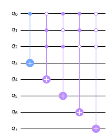
After all 1408 MCX, the circuit adds an other MCX on the target qubit
controlled by all ancillas with all control states set to 0. The target qubit
is therefore introduced a phase shift when all ancillas are in |0>.
Here, the target qubit is represented by q8, see how the q8’s gate is active
only if all ancillas are |0>:
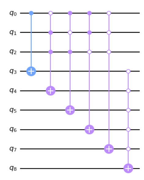
So we want all ancillas to be |0> but it is also their original state. We
therfore have to influence the control qubits of each MCX so that none actually
performs the X gate on any ancilla. This means that among all control qubits of
a MCX, at least one must have a state different from its control state, thus
deactivating the gate.
Remember, inputs must be different from their control state specified on the
gate. Therefore a qubit marked as False, must take value |0> to deactivate
the gate since False, gives the qubit a control state of 1. Similarly, a qubit marked True must take value |1>.
So we said earlier that the MCX have either 3 or 1 control bits and that at least 1 of the control qubits must mismatch from their control state.
POC with trivial qubits
Obviously this results in an equation system but let’s see what we get with only the obvious qubits: the ones controlling an ancilla by themselves.
Indeed if an ancilla is controlled by a single input qubit then this qubit MUST
be different from his control state so the X gate stays disabled. Therefore, any input qubit marked as False and as the only control of a gate MUST be set to |0> to match the oracle. Same is true for qubits marked as True that must be in state |1>.
We can illustrate this with the circuit below: q3 MUST be set to |0> so the
gate must be deactivated, so q0 MUST be |0> (control state 1) to deactivate
the gate.
So let’s try to set all obvious qubits:
#!/usr/bin/env python3
import json

with open('circuit.json', 'r') as f:
    j = json.load(f)

nq = j['memory']

system = ['0'] * nq

for cs in j['circuit']:
    if len(cs) == 1:
        system[cs[0][1]] = '1' if cs[0][0] else '0'


system.reverse()
result = "".join(system)

print(int.to_bytes(int(result, 2), nq//8, 'little'))
Well, most of them are 0, except, the first byte: z
Which is a good sign that we are indeed decoding a flag of the form
zer0pts{...}
Equation system
For MCX with 3 control qubits, we simply need to put them in an equation system alongside the trivial qubits.
We will have a total of 1408 equations, 1 for each MCX, each equation basically saying that at least 1 qubit must be different from its control state, and therefore equal to its assigned boolean in the json.
Let’s take the same circuit again, we will have the following system:
q0 == 0
q0 == 1 OR q1 == 0 OR q2 == 0
q0 == 0 OR q1 == 1 OR q2 == 0
q0 == 0 OR q1 == 0 OR q2 == 1
q0 == 1 OR q1 == 1 OR q2 == 1
note: The above system does not have a unique solution, but adding the rest of
the circuit will make the solution unique.
Once the system is solved, we will know the state of all qubits that match the oracle, which is the one outputed by the quantum circuit. We will then be able to decode it to get the flag.
Solve
I used z3 to build and solve the equation system:
#!/usr/bin/env python3
import json
from z3 import *

with open('circuit.json', 'r') as f:
    j = json.load(f)

nq = j['memory']

system = [Bool(str(i)) for i in range(nq)]

s = Solver()

for cs in j['circuit']:
    term = Or()
    for c in cs:
        term = Or(term, system[c[1]] == c[0])
    s.add(term)

print(s)
print(s.check())

m = s.model()

result_arr = [''] * nq

for d in m.decls():
    result_arr[int(d.name())] = '1' if m[d] else '0'

result_arr.reverse()
result = "".join(result_arr)

print(int.to_bytes(int(result, 2), nq//8, 'little'))
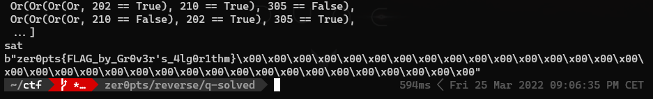
Running the script outputs us the equation system, sat indicating that z3 found
a solution to the system and the decoded solution of the system with the flag:
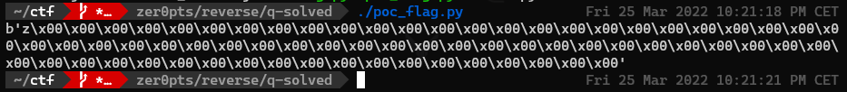
zer0pts{FLAG_by_Gr0v3r's_4lg0r1thm}